Chroma 63110A Electronic Load Module
Our Part #19228.1
Condition:New
Mfr Part #63110A
- Description
- Specifications
- Documents
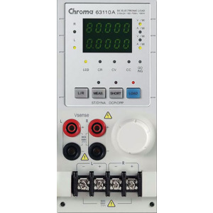
Chroma 63110A DC Electronic Load with LED Simulation
- 2A, 500V, 100W max., Dual Channel
- Unique LED mode for LED power driver test
- Programmable LED operating resistance (Rd)
- Programmable internal resistance (Rr) for simulating LED ripple current
- Fast response for PWM dimming test
- Up to eight channels in one mainframe
- 16-bit precision voltage and current measurement with dual-range
- Full Protection: OC, OP, OT protection and OV alarm
- Must be used with the 6312A or 6314A Mainframe
LED Load Simulator for LED Power Driver Test
Chroma has created the industry's first LED operating mode for simulating LED loading with the 63110A load model from their 6310A series Electronic Loads. By setting the LED driver's output voltage, and current, the Electronic Load can simulate the LED's loading characteristics. The LED's forward voltage and operating resistance can also be set to further adjust the loading current and ripple current to better simulate LED characteristics. The 63110A design also has increased bandwidth to allow for PWM dimming testing.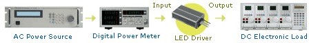
Problems found in using other manufacturers' E-Loads or LEDs for testing drivers
As a constant current source, the LED driver has an output voltage range with a constant output current. LED drivers are usually tested in one of the following ways:
- With LEDs
- Using resistors for loading
- Using Electronic Loads in Constant Resistance (CR) mode, or Constant Voltage (CV) mode
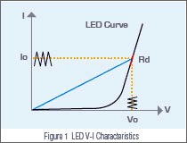 As shown on the V-I curve in figure 1, the LED has a forward voltage VF and an operating resistance (Rd). When using a resistor as loading, the V-I curve of the resistor is not able to simulate the V-I curve of the LED as shown in blue on figure 1. The LED driver may not start due to the difference in V-I characteristic between the resistors and the LEDs. When using Electronic Loads, the CR and CV mode settings are set for when the LED is under stable operation and therefore, is unable to simulate turn on or PWM brightness control characteristics. This may cause the LED driver to function improperly or trigger its protection circuits. These testing requirements can be achieved when using a LEDs as a load; however, issues regarding the LED aging as well as different LED drivers may require different types of LEDs or a number of LEDs, making it inconvenient for mass production testing.
Chroma's Solution
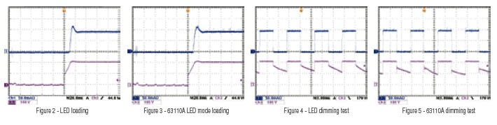
Figure 2 shows the current waveform from a LED load. Figure 3 shows the current waveform from 63110A's LED mode load function. From figures 2 and 3, the start up voltage and current of the LED driver is very similar. Figure 4 shows the dimming current waveform of the LED. Figure 5 shows the dimming current waveform when using 63110A as a load.
The internal resistance (Rr) can be adjusted to simulate the LED driver output ripple current. The traditional E-load can not simulate the ripple current of LED shown as Figure 6. Figure 7 shows the ripple current waveform from a LED load. Figure 8 shows the ripple current waveform from the 63110A LED mode load function.
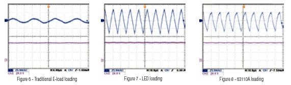
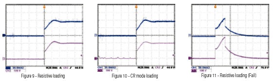
Figure 9 shows the current waveform from a resistive load. Figure 10 shows the current waveform from a CR mode of an Electronic Load loading. Figure 9 and 10 current waveform differs significantly from that of LED loading, especially the voltage and current overshoot, which may cause the LED driver to go into protection. Using resistive load or CR mode to test LED drivers may cause the LED drivers to fail to turn on as shown in Figure 11.
Conclusion
Most E-Load manufacturers have similar designs but are unable to simulate the I-V curve of the LED as well as internal capacitances causing abnormal OCP, OVP. Therefore, other E-Loads are not suitable for testing LED drivers.
The 63110A was specifically designed to simulate LED characteristics to test the functions of LED drivers. Not only can it test in stable conditions, it can also test turn on, PWM dimming characteristics of the LED driver and the Rd value can be adjusted according to the LED V-I curve making it an irreplaceable load choice for LED driver testing.
| Specifications | ||||
| Model | 63110A (100Wx2) | 63113A | ||
| Power | 100 W | 300 W | ||
| Current | 0 to 0.6A | 0 to 2A | 0 to 5A | 0 to 20A |
| Voltage *1 | 0 to 500V | 0 to 300V | ||
| Min. Operating Voltage | 6V@2A | 4V@20A | ||
| LED Mode | ||||
| Range | Operation Voltage: 0 to 100V/0 to 500V Rd Coefficien: 0.001 to 1 VF: 0 to 100V/0 to 500V Current: 0 to 2A Rd: 1Ω to 1 kΩ/10Ω to 10kΩ | Operating Voltage: 0 to 60V/0 to 300V Rd Coefficient: 0.001 to 1 Vf: 0 to 60V/0 to 300V LEDL @ CCH: 0 to 60V- 0 to 20A (Rd: 0.05Ω to 50Ω ) LEDL @ CCL: 0 to 60V- 0 to 5A (Rd: 0.8Ω to 800Ω ) LEDH @ CCL: 0 to 300V- 0 to 5A (Rd: 4Ω to 4kΩ ) | ||
| Resolution *2 | ||||
| Constant Resistance Mode | ||||
| Range | CRL: 3Ω to 1kΩ (100W/100V) CRH: 10Ω to 10kΩ (100W/500V) | CRL @ CC: 0.2Ω to 200Ω (300W/60V) CRL @ CCL: 0.8Ω to 800Ω (300W/60V) CRH @ CC: 4Ω to 4kΩ (300W/300V) | ||
| Resolution*2 | CRL: 62.5μS CRH: 6.25μS | CRL @ CCH: 100μS CRL @ CCL: 25μS CRH @ CCL: 5μS | ||
| Accuracy | 1kΩ: 4mS+0.2% 10kΩ: 1mS+0.1% | 200Ω: 0.2% (setting + range) 800Ω: 0.2% (setting + range) 4kΩ: 0.2% (setting + range) | ||
| Constant Voltage Mode | ||||
| Range | 0 to 500V | 0 to 300V | ||
| Resolution | 20mV | 6mV | ||
| Accuracy | 0.05% + 0.1%F.S. | 0.05% + 0.1%F.S. | ||
| Constant Current Mode | ||||
| Range | 0 to 0.6A | 0 to 2A | 0 to 5A | 0 to 20A |
| Resolution*2 | 12μA | 40μA | 100μA | 400μA |
| Accuracy | 0.1%+0.1% F.S. | 0.1%+0.1% F.S. | 0.1%±0.2% F.S. | |
| Measurement Section | ||||
| Voltage Read Back | ||||
| Range | 0 to 100V | 0 to 500V | 0 to 60V | 0 to 300V |
| Resolution | 2mV | 10mV | 1.2mV | 6mV |
| Accuracy | 0.025%+0.025% F.S. | 0.025%+0.025% F.S. | ||
| Current Read Back | ||||
| Range | 0 to 0.6A | 0 to 2A | 0 to 5A | 0 to 20A |
| Resolution | 12μA | 40μA | 100μA | 400μA |
| Accuracy | 0.05%+0.05% F.S. | 0.05%+0.05% F.S. | ||
*1 If the operating voltage exceeds 1.1 times of the rated voltage, it would cause permanent damage to the device.
*2 S (siemens) is the SI unit of conductance, equal to one reciprocal ohm.